Wire Antenna Calculator
Instructions:
- Enter the desired resonant or center frequency of your choice upper input of the form.
- In the pull-down, choose the Vee Angle you wish to use.
- Calculate Button: Displays needed calculations for your chosen vee angle.
- The correct lengths for the various antenna types will be displayed in the charts.
- To better understand the variables be sure to read the application notes and study the drawings below.
- This calculator will accurately compute values for all High Frequency antennas from 1.8 mHz to 30 mHz.
- Clear Button: Clears all contents from the screen.
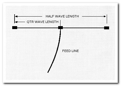
Dipoles and Inverted Vees
The basic formula for determining the length of a center fed, half-wave wire Dipole, or Inverted Vee antenna is:
468 ÷ Freq (mHz) = Length (feet).
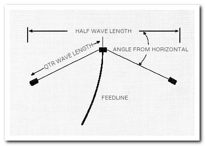
This formula takes into consideration the capacitive "end-effect" from insulators which shortens the physical length requirement for the equivalent electrical length. The inverted Vee antenna will be shorter by 2 - 5% depending on the angle from horizontal.
| Half-wave Flat Top Dipole | Half-wave Inverted Vee Dipole | |
 |
 |
The feed point impedance of a Dipole in free space is close to 75Ω. Dipoles can be fed directly with 50Ω or 75Ω coax, or with a 1:1 balun at the feed point. The slight mismatch when using 50Ω coax can be easily matched with an antenna tuner. More importantly, for symmetrical current distribution, reduced feed line radiation, and thus a cleaner pattern, a balun should always be used at the feed point. Due to the proximity to ground at the end of each leg, the feed point impedance of an Inverted Vee is very close to 50Ω. Inverted Vees thus can be fed with 50Ω coaxial cable, with or without a 1:1 balun (The advice regarding the use a feed point balun pertains to the Inverted Vee as well). Both Dipoles and Inverted Vees can be fed with 300Ω or 450Ω ladder or open wire feeders into a balanced Antenna Tuner. This configuration, known as a "Doublet", will work well as a multi-band antenna. Flat-Top Dipole or Inverted Vee? As is often the case when given a choice, there are trade-offs involved. The Inverted-Vee requires only one tall support, and less horizontal spread than the Flat-Top Dipole. It is also a very close match to 50Ω coax. On the other hand there is some loss of gain because the pattern is less directional, and the bandwidth is narrower than the the horizontal dipole.
Dipole Construction Notes
Half-wave Dipoles and Inverted Vees are very easy to construct, and are great for homebrew projects. You may purchase commercially made end insulators and center insulators with coax connectors built in, but why not make it truly homebrew and make your own hardware? It is quite easy using schedule 40 PVC pipe. Admittedly, if you are going to use a balun at the feed point, purchasing a center insulator with the balun built in is certainly a lot less work! If you decide to build your own, be sure all connections are secure, both mechanically and electrically. Be sure to properly solder all joints and to use weatherproofing. Remember to provide some type of strain relief at the center insulator for your "dangling" feed line. Not only does the feed line represent a strong downward tug, but when the wind blows the mechanical stress on your connections increases dramatically. A good strain relief system is to wrap the feed cable once around the center insulator and secure it with UV-Resistant (usually black) tie-wraps. Suitable feed line can be 50Ω coax, such as RG-58, RG-8X, RG-8, RG-213, or 75Ω types such as RG-11, RG-59, RG-6, or even 75 ohm twin lead. Believe it or not, even zip cord (lamp cord) will perform quite well. Of course you need to "size" your feed line according to the power you intend to run. Power in excess of 200 watts will develop very high RF voltages. Be sure your feed lines and antenna hardware can handle the power. In the real world, where you build your antennas, the actual impedance of your wire antennas will depend on several variables. i.e. height above ground, proximity to large, especially metallic, objects, and proximity to other resonant antennas. When making your antenna, always cut your lengths a bit long. This will allow you to "fine tune" the antenna by trimming. You will quickly learn that "trimming" is a LOT easier than "adding to"! When you decide where to "hang" your antenna, remember that the horizontal radiation pattern of a Dipole in free space is a wide "Figure-8", which radiates perpendicular to the axis of the dipole. The vertical radiation pattern depends on the height above ground. As stated above, to be an effective DX antenna, a low-angle signal take-off is required, and that means your dipole must be at least one-half wavelength above ground. If you choose to build an Inverted Vee, be sure the angle of the sloping legs is not more than 45 degrees (the inside angle at the feed point is not less than 90 degrees). If you increase the slope more than this, the Inverted Vee will begin to act like a vertical monopole with an omnidirectional radiation pattern. Finally, don't fret about fractional parts of an inch when using the measurements from the calculator above. At HF frequencies, an inch is such a small part of a wavelength that it is a non issue.
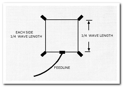
Full Wave Loops
The basic formula for determining the length of a full-wave wire Loop antenna is:
1005 ÷ freq (mHz) = Length (feet).
Since closed loops are not subject to "end-effect" the calculated physical lengths with this formula are longer than corresponding dipole dimensions and are close to free space dimensions. Since the loop dimensions are larger than those of a half-wave dipole, the radiation efficiency is also higher.
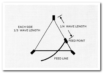
| Full-wave Quad Loop | Full-wave Delta Loop | |
 |
 |
The feed point impedance of a full-wave loop in free space is approximately 100Ω - 120Ω with a gain over a dipole of 1.35 dB. In the real world, installed at practical amateur heights (physically close to ground), the range of feed point impedance can be from 50Ω - 240Ω depending on configuration, orientation, and choice of feed point. One of the realities that comes with choosing a full-wave loop is the need for some type of feed point matching system. If you study the literature you will discover a near endless array of configurations for a full-wave loop. You can choose a square or diamond, equilateral triangle with apex up or down, feed point on the bottom, side, corner... All these "adjustments" affect the feed impedance, gain, polarization, pattern, and of course, the support structure requirements. For our purposes, we will limit this discussion to two configurations, both optimized for certain HF bands.
- The bottom-fed quad loop is a very good choice for the 20-10M bands. It has the highest gain at low take-off angles, and the horizontal polarization is great for these frequencies.
- The off-corner fed, equilateral delta is a solid performer on the amateur frequencies below 20M. With its low angle take-off, vertical polarization,and single support requirement, it is a great choice for low band DXers. Study the literature. You may find another configuration more suited to your requirements.
At take-off angles of interest to DXers, the full-wave loop's horizontal radiation pattern in free space is a wide "Figure-8" which radiates perpendicular to the plane of the loop. Interestingly, at very low angles, some radiation from the delta loop is end-fire... that is, parallel with the plane of the loop. Of course, to achieve such low angles would require the entire loop to be mounted at least one quarter wavelength above ground. That would be quite a challenge at 3.5 and 1.8 mHz!
Full Wave Construction Notes
Because of their size, full-wave loops present additional challenges to the builder. Basically, all the dipole construction notes above, pertain to loop construction as well. There is no substitute for good engineering practice, and common sense still rules the day. There are however, a few considerations unique to the loop. Because of the large size of low frequency loops, the length of the feed line represents a significant load on the wire element. This is especially true for high power levels when larger coax is required. You should carefully design the feed point mechanics for strength. One solution which solves two design issues, is to use heavy duty ladder line, and feed the antenna through a balanced antenna tuner. This solves the weight problem as well as the need for a feed point matching system. If you don't have a sufficiently tall support structure for a full-wave loop, don't despair. There is significant empirical testimony to the efficacy of a low-to-the-ground, sloping delta loop. Modeling will confirm a 1-3 dB gain in directivity in the direction of the slope.
Conclusion
All-in-all, full-wave loops are very good antennas. If you feel like experimenting, or if your low-band antenna farm needs a bit of improvement, by all means try a loop. If you always wanted to try 80 Meters, here's your chance.